In my last post we focused on the affect that tolerances have on the price of a part produced in a machine shop. In this post, I would like to examine what happens when the design software you use departs from the reality of machine shop practices. What does this mean? Simply put, it is when the designer can simply and quickly design a part which looks fantastic on the monitor, but completely ignores, or is unaware of, the processes involved in making a part.
As a user of one of the world’s leading design packages I am always impressed with how powerful CAD (Computer Aided Design) systems are. The user can quickly and efficiently design a part that is both functional and aesthetically pleasing. Organic shapes are easy to produce and designs are only limited by your vision and your ability with the software. However, the most important lesson to learn with these systems is that the ability to design whatever your imagination can conceive, does not mean it will translate well from your desktop computer to our CNC machine. The machine shop will always try it’s best to give you what you want, but you might not like the price.
There are a number of pitfalls that can happen when designing a part in CAD without understanding manufacturing practices. The one I will address in this article is what I refer to as “the default syndrome.” This happens when the defaults for regular commands, such as filleting, are left at the default setting. In our software package that happens to be .100”. You would all agree that everyone wants a part that is nice to hold and feels good to the touch; that is just good design practice. As well, you might need fillets to add strength to a part where sharp corners might lead to fractures or failure. Again, good design practice and necessary in many instances. Let’s look at an example. To add some fillets to his or her design, for either cosmetic or functional reasons, the designer decides to fillet all the corners of the box they have modeled on both the internal and external surfaces. Press the fillet radio button, click on all the edges that you want to fillet and there you go, easy. One simple click and your design looks great. That is until it gets to my desk for quoting.
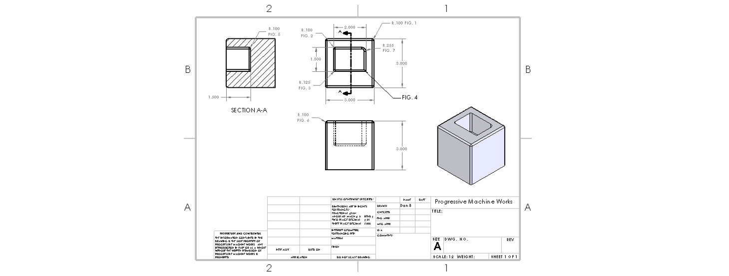
You might ask then, “What’s wrong with a .100 fillet?” Well, the answer to that depends on where you put the fillet and also how it blends into other features. Let’s consider the drawing below. It would seem that the part is pretty straight forward; a block with a pocket and some fillets all around. It is straight forward until you need to produce the required fillets on a number of the features. In figure 1, you will see defined a .100 radius on the outside corners of the box. For a CNC machine, that is fairly easy to make. We simply program the cutter to walk around the outside of the box and we include the radius in the tool path. That one is easy but what about the .100 radius around the top of the box? (Fig. 6) Not as easy as it may seem.
I have two options to choose from when producing this fillet. The first is to purchase a cutter with a .100 radius already ground into the cutter. The problem here is that not many cutter manufacturers make a cutter like that. I can readily buy a cutter that has a .125 radius, or a cutter that has a .062 radius but not one that has a .100 rad. These are usually custom orders and are weeks away and costly. If you need hundreds of these boxes this is not that critical as the cost of the tool is amortized over many parts. If you need five parts however, it gets expensive on a per part basis. At the very least, a skilled machinist may grind his own cutter but that takes time and costs money too. As well, machinists with the necessary skill to grind a cutter like that are becoming a rarity.
You may say that the .125 radius is close enough for the function of the box, but I cannot assume that as I am rarely aware of a parts function. Also, the drawing shows a three place decimal value which limits me to +/-.005 according to the drawing call out. Even a two place decimal value leaves me outside the tolerance allowance according to the drawing. Remember, I will rarely know what your part is meant to do and I cannot make assumptions as to what is permissible or not. The drawing is supposed to speak for you.
My second option in producing this fillet is to surface machine it. That means I will use a ball nose cutter to make many cuts along the top of the box to approximate the .100 radius. This is a time consuming process. Again, time is money. The best solution would be for the designer to be aware of what is available for standard tooling. Knowing this, they may have easily changed the design to incorporate the .125 radius as opposed to the .100 radius that was the default setting. Understandably, the designer cannot always have this information on hand so it is important to check with machine shop while you’re designing. I might also suggest that a chamfer on this feature would be much easier to make.
Another issue that arises in our sample box is the pocket. The pocket is 1.5 inches deep and it specifies three different radius values in the corners: .100, .125 and .255 (Fig. 2) Theoretically it is possible to produce all three of those corner radii but let’s consider what it would take. Looking in my tool box I find I have a selection of cutters of various diameters. For the .125 rad. I could easily use a .250 diameter end mill, which is easily purchased from many of our suppliers. The challenge for me is the depth of the pocket. As a pocket gets deeper, the cutters ability to remain rigid and not flex is curtailed. This leads to deflection of the cutter and inevitably chatter marks in the corners or incorrect sizes. In our example, the problem gets worse as I now need to use a 3/16 diameter end mill to do the .100 corner. The length to diameter ratio at that point is also 8:1. Not very machine friendly; imagine machining with a noodle. There are cutters available to do this job but they are not always on hand at our local supplier. These types of features also take longer to produce and they will cost you more. The largest radius that you can use to create an effective design is always the best course.
One of the more unusual, but common, design errors that I see is pockets drawn with square corners. Unless you want to spend lots of money on Electro Discharge Machining (EDM), stay away from those as they cannot be machined using standard methods. If you need the mating part to fit in the corner, as it has sharp corners, consider an undercut on the corners of the pocket you are designing.
One more problem with this design is the corner radius shown at the bottom of the pocket. (Fig. 5) This feature is almost impossible to machine with standard machining techniques as drawn. We can source end mills with corner rads. ground into them, but the end mill has to be big enough to both reach down to the bottom of the pocket and to accommodate the .100 radius. A quick check in my tool catalogue tells me that I can get a .250 diameter end mill with a .100 corner radius. This will allow us to mill the entire pocket except the .100 radius on the side wall corner. Can we make this feature as drawn? Probably, but it will cost you as it will be difficult and time consuming.
Perhaps the second best advice that I can give a designer, when it comes to specifying what radius to use, is to make themselves familiar with the machining process and the tools that are available. To achieve cost effective production you cannot simply apply radii to all your corners “willy-nilly” as they say. The best advice I can give is to ask the expert. Consult with your machine shop if you have a concern about the machinability of your design, and you might find that your costs can be reduced significantly with a few design changes. We are here to help and our experience in manufacturing is at your disposal. We all succeed when we work together.